Directional Mixer
This tools applies $S$ max-$r_E$ beampatterns to the Ambisonic sound scene. It can be used as an Ambisonic “directional mixer”. This means that a directional filtering is operated to enhance and reduce some directions according to the chosen beampatterns1. The proposed beampatterns are on-axis normalized max-$r_E$ beampatterns of degree $L_1$
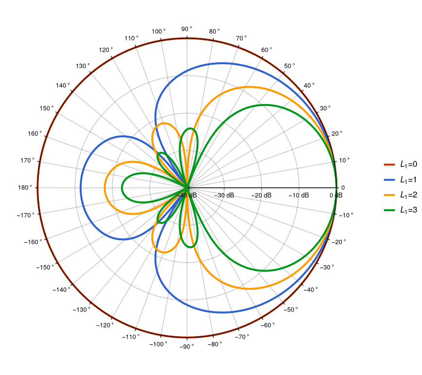
as shown in Fig.1. They have an high side-lobe attenuation while maintaining a narrow main lobe2. For $L_1 = 0$ the beampattern is omnidirectional. The higher the beampattern degree, the more selective the directionnal filtering. At execution time, the steering angles ($\theta, \phi)$, the degree $L_1$ as well as the gain in dB of the each $S$ beampatterns can be changed. This directional filtering effect requires a higher degree of re-expansion $\tilde{L}$ for the filtered sound scene such that1:
\[\begin{equation} \tilde{L} = L + L_1, \end{equation}\]where $L$ is the input Ambisonic sound scene degree and $L_1$ is the beampattern degree. However, it is possible to choose the same degree for the output ($\tilde{L} = L$) with reasonable results.
Compilation parameters
S: number of beampatterns to apply on the input sound scene,L: maximal Spherical Harmonics degree for the input $(L > 0)$,L1: maximal max-$r_E$ beampatterns degree ($L1 \geq 0$).
In the current implemtation $L + L1 \leq 10$.
Warning: the compilation can last several hours as $L_1$ and $S$ increase. Don’t forget the flag -t 0 with the faust2... scripts.
Inputs / Outputs
- Inputs: $(L+1)^2$
- Outputs: $(L+L_1+1)^2$ or $(L+1)^2$
User Interface
For the $i$-th beampattern:
| Element | OSC | Min value | Max value |
|---|---|---|---|
| Gain (dB) | gain_i |
-10 | 10 |
| Azimuth $\theta$ ($^\circ$) | azimuth_i |
-180 | 180 |
| Elevation $\phi$ ($^\circ$) | elevation_i |
-90 | 90 |
| Degree $L_1$ | degree_i |
0 | L1 |
| On | on_i |
0 | 1 |
Example of use
Let’s start with a sound scene a degree $L = 7$ composed of several unit-amplitude plane waves with various direction of arrival.
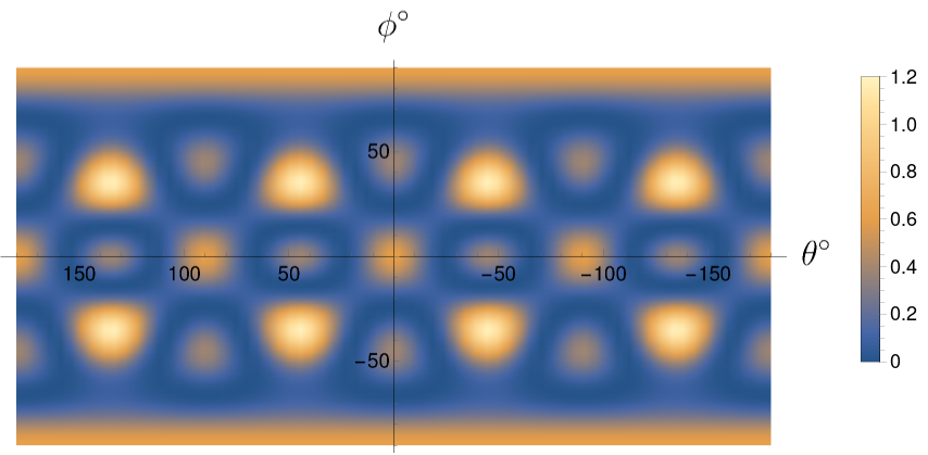
The square normalized amplitude of this scene is shown in Fig.2. Now we apply two max-$r_E$ beampatterns on this scene:
- Beampattern 1: degree $L_{1,1} = 1$, of amplitude $g_1 = 0$ dB, steering angles ($\theta_1 = -135^\circ$, $\phi_1 = 45^\circ$),
- Beampattern 2: degree $L_{1,1} = 2$, of amplitude $g_2 = 10$ dB, steering angles ($\theta_2 = 75^\circ$, $\phi_2 = 0^\circ$).
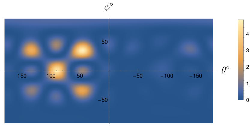
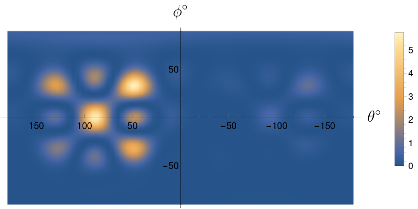
The square normalized amplitude of the resulting sound scene is shown in Fig.3 at degree $\tilde{L} = 7$ and in Fig.4 at degree $\tilde{L} = 9$.
-
P. Lecomte, P.-A. Gauthier, A. Berry, A. Garcia, et C. Langrenne, « Directional filtering of Ambisonic sound scenes », in Audio Engineering Society Conference: Spatial Reproduction, Tokyo, 2018, p. 1‑9. ↩ ↩2
-
J. Daniel, J.-B. Rault, et J.-D. Polack, « Ambisonics encoding of other audio formats for multiple listening conditions », in Audio Engineering Society Convention 105, San Francisco, 1998, p. 1‑29. ↩